
Home > On-Demand Archives > Talks >
Spectrometer Signal Processing Systems for NASA Space Applications
Damon Bradley - Watch Now - DSP Online Conference 2020 - Duration: 54:15
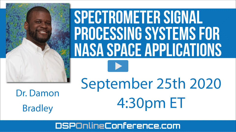
For many NASA Space Science Instruments flown aboard various spacecraft, digital spectrometers are a very common instrument class. These instruments are used for a vast array of scientific monitoring and observational applications, such as detecting organic compounds on distant planetary satellites in the solar system, measuring solar plasma interaction with the surface of our own Moon, monitoring geophysical parameters here on Earth, and determining the composition of exoplanet atmospheres several light years away. In particular, these instruments process signals arising from a vast swath of the radio spectrum, covering frequencies from near DC all the way up to sub-mm THz frequencies. Moreover, these systems must operate under extreme conditions of temperature and radiation environment, while also performing efficient computation under severe power constraints. This talk will cover practical implementation of digital spectrometers for these space applications, as well as some of the statistical signal processing methods used for detecting various phenomena in-orbit for particular Earth-observing instruments.
Dear S.Sharif:
Thanks for attending. I'm very happy you enjoyed my talk. My former colleague in this field, Adriano, has a really good paper on this: https://www.mdpi.com/1999-4893/2/3/1248/htm
Typically, wavelet denoising is used for just that - taking out noise. However, in our application, the signal we want IS the noise, and we don't want any other signals, hence the idea of somehow using wavelet denoising to "de-signal" the noise corrupted by the signal.
The use of kurtosis to detect nonGaussian signals in the radiometer noise measurement is unrelated to the wavelet research.
Thank you again Dr. Bardley for the reply and paper suggestion, I will definitely check it out.
Hello, thanks for very interesting talk. during Q&A session you mentioned the fact that some of your colleagues are working on Risc-V, Risc-V looks very interesting in many ways, but working in avionics it is quite hard to find devices for high temperature, so I was curious how you could find those core hardened ? Do you have labs that able to have the Risc-V core on SoI (Silicon on Insulator) or even SoC (Silicon on Carbide) or other process for extreme environement ?
thanks
Thanks for attending! And not yet - but we're looking into it. Please get my contact information from Stephane and we can chat further about this!
Sure, thanks for your answer.
No offense to all of the other excellent presentations, but this has to be the coolest application yet for advanced signal processing. Great presentation!
I'm curious though, you mentioned getting space qualified parts (I had experience long ago with rad-hard design). With the advent of commercial space operators (SpaceX et al) as well as the growth in satellites (not a fan due to RFI & light pollution from them) made the technology lag less by increasing demand? OTOH sounds like you've found ways to be really clever to make old technology keep pace by rethinking the design so maybe it's not a problem?
Thank you so much! I'm glad you enjoyed the talk!
The technology certainly isn't lag-less, and perhaps now, with new players entering the field of commercial space technology, this situation will actually improve. We certainly hope so, and there are a lot of initiatives government and otherwise that are working to improve the overall situaiton.
Hello, thank for the talk.
In the digital downconversion, how is wc (LO freq) chosen?
There are several LO's involved. Normally, we choose a minimal set of LO's that 1) do not interfere with our radiometer band, 2) conveniently shift the radiometric bandwidth down to a set of frequencies that can be acquired by an ADC. Sometimes, we downconvert digitally as well so that we can lower the subsequent clock rate.
Thanks for attending!
All downconversion is typically done in stages, and is a matter of convenience and efficiency so we can eventually lower the data rate and hence spacecraft power consumption of the instrument.
thanks again!
In the Polarimetric digital radiometer slide, the downconversion was after ADC. Sole purpose of this downconversion is to lower the subsequent clock rate?
In general, if the ADC is fast enough and operates at high enough bandwidth, we don't need to perform RF downconversion. In the block diagram, I abstracted away the RF downconversion that normally converts the RF bandwidth to an IF bandwith. Typically, we have 2 stages of downconversion, but that's changing now since we have ADC's that can operate in L-Band and even higher.
Stupid question, why cant the bank of dig filters be substituted with a FFT module?
Never a stupid question!
This is exactly what we're using - a Polyphase Filterbank, which is basically a FFT spectrometer that has a windowing function applied to it. I forgot to mention that we're specifically using a critically-sampled polyphase filterbank, so we're operating at a minimum sample rate.
Got it, thanks!
My pleasure. Keep the questions coming!
Thank you Dr. Bradley for the talk it was very informative, inspiring, and cool! Lots of new information to digest.
Few questions regarding the spinoff research that stemmed from SMAP, I noticed wavelet denoising is used for cancelation purposes and was wondering if you can elaborate on that a bit more. Also what is the reason for using wavelets if Kurtosis is being used for time-frequency analysis. Thank you again