Home > Q&A Sessions >
Live Q&A - Digital Signal Processing for Satellite Communications
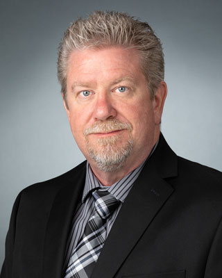
Bradford Watson- Recording Soon Available - DSP Online Conference 2024

Thank you! I appreciate the feedback.
I've found your books very useful as well, especially Streamlining Digital Signal Processing.
Could you please elaborate more on the users or logical channels you mentioned? How do these ideas relate to frequency reuse (e.g., the 4-color scheme)? What are the requirements for guard bands to avoid inter-channel interference? Thanks!
It's a complicated question, because different systems do things in different ways with different schemes, depending on how users are allocated spectrum (or share spectrum). The generic idea that I presented was the idea of "logical channels", meaning that a user is allocated a chunk of spectrum for a given beam. The logical channel for each user is just an identifier and doesn't really specify what frequency it occupies within a beam's bandwidth. The system (via ground software running at the gateway) manages each of the logical channels and assigns them to frequency regions across the beam when setting up and tearing down calls. Typically this bandwidth allocation also includes guardbands, which, in my experience, are usually around 1 MHz. So the user spectrum must be fully masked off (say, -60 dB attenuated) within +/- 1MHz of the bandwidth allocated to avoid logical channel crosstalk. As part of the logical channel frequency assignment, individual subchannels in the channelizers and reconstructors are selected that are associated with the logical channels. This is usually done at the spacecraft level. So, for each logical channel, there are a set of contiguous-in-frequency subchannels that are associated with it. It is these subchannels that are routed around the payload to provide the connectivity.
As an example, let's say our spacecraft channelizer's subchannel size is 1 MHz. User A needs 20 MHz of bandwidth, and User B needs 10 MHz of bandwidth. User A would be assigned 20 subchannels plus 2x1MHz subchannel (one on each side) as guardbands for a total of 22 subchannels. This group of 22 subchannels would be designated Logical Channel 1. Likewise, User B would be assigned 10 + 2 = 12 subchannels to cover it's bandwidth and guardbands, and assigned Logical Channel 2. Logical Channels 1 and 2 are concatenated or mapped to the frequency spectrum in some way and uplinked to the spacecraft. These Logical Channels are extracted by the channelizer, and the subchannels associated with them are routed to some other place (like another geographically located beam) for downlink. For the downlink, the subchannels associated with a given Logical Channel are put into the reconstructor at some pre-defined frequency (along with other Logical Channels), and the entire spectrum is re-assembled (e.g., synthesized, or reconstructed), and downlinked.
Hopefully this answers your question.
Thanks so much for giving this talk, it was great to listen to.
Many years ago, I worked on ground segment gateway software for a geo-stationary satellite telephony system (which I believe is still in use primarily for radio applications in hard-to-reach places). My software was pretty far downstream from the signal processing - call setup processing and authentication checks, and things like that. Now, in a completely different industry, I'm getting to work a little DSP, and seeing your presentation from those perspectives was really enjoyable.
Allen Kwiatkowski
Thanks for listening! It's an interesting subject, and enjoyable to present. I appreciate your comment.
In your presentation you mention a polyphase down sampling block. The output of this block after down-sampling has about 80% of the Nyquist zone as usable spectrum.
Assuming you use Matlab, would you post a simple design example?
I realize that a half-band filter is the simplest case of this. So I guess slightly more sophisticated.
Sure, I'm happy to. Pasted below is one of the examples from my book that describes a 16-path polyphase filter using a Kaiser filter as the prototype. It compares the polyphase implementation against a standard implementation and shows that the error is really small:
% polyphase decimator implementing prototype filter as two matrices
clear
close all
%% set parameters
Fs = 100;
N = 16; % FFT size for both the channelizer and reconstructor
%% channelizer parameters
Fs_out = Fs/N; % output sample rate
BW = Fs_out0.8; % pick a filter bandwidth something less than the sample rate
%% make a prototype filter
pb_ripple = 0.01;
sb_atten = -60;
% build filter
[nk,Wnk,btak,filtypek] = kaiserord( [BW/2 Fs_out/2], [1 0], [10^(pb_ripple/20)-1 10^(sb_atten/20)], Fs );
if mod(nk,2) ~= 0, nk = nk + 1; end % prefer odd length filters (but can use even length filters)
h = fir1(nk, Wnk, filtypek, kaiser(nk+1,btak), 'noscale'); % make the filter
num_pad_zeros = ceil(length(h)/N)N-length(h); % make some pading zeros so we can do the ppf decomp
h = [zeros(1,floor(num_pad_zeros/2)+1) h zeros(1,floor(num_pad_zeros/2))]; % pad it
h_poly = reshape(h, N, length(h)/N); % do the polyphase decomposition of the filter
%% make some data
x = randn(1,N*1000);
x_poly = flipud(reshape(x, N, length(x)/N)); % do the polphase decomposition of the data, but flip it
%% implement the polyphase decimator by convolving the rows of each matrix
for k = 1:N
y(k,:) = conv(x_poly(k,:), h_poly(k,:));
end
y_out = sum(y); % sum over columns to create the polyphase decimator
y_out1 = downsample(conv(x,h), N, N-1); % create some truth data to compare; decimation phase is important here
disp(['error = ' num2str(sum(abs(y_out-y_out1)))]) % note how small this is
return
The Q&A may be boring. Each time a question came to mind, it was then addressed within the presentation. Excellent job! Thank you!
Not boring at all! I had a lot of good engagement. Thanks for listening!


Hello Bradford. Very informative and professional presentation. Thank you so much.